Purpose
To evaluate the quality of an image of a grating target placed in a model eye and viewed through implanted toric intraocular lenses (IOLs).
Design
Laboratory investigation.
Methods
Toric IOLs, SN6AT5 with a cylinder power of 3.0 diopters (3.0 D, Alcon), ST6AT9 (6.0 D, Alcon), 311T5 (3.0 D, HOYA), or 311T9 (6.0 D, HOYA), were placed in a fluid-filled model eye. A United States Air Force test target was placed internally on the posterior surface of the model eye. A flat contact lens or a wide-angle contact lens was placed on the cornea. The contrast and length of the grating targets perpendicular (vertical) or parallel (horizontal) to the flat meridian of the toric IOL were compared with those obtained through aspheric IOLs.
Results
The contrast of the targets viewed through the flat contact lens and toric IOLs in the vertical direction was significantly lower than that viewed through the aspheric IOL at 16 cycle/mm (SN6AT9, P = .002; SN6AT5, P = .028; 311T9, P = .002; 311T5, P = .011) but not with the wide-angle viewing lens at 16, 32, and 64 cycle/mm. The vertical length of the target with a flat contact lens was longer and the horizontal length was shorter than that through the aspheric IOL by 1% to 3% with the SN6AT5 and 311T5 IOLs and by 3% to 5% with the SN6AT9 and 311T9 IOLs. However, the vertical and horizontal lengths were not significantly different through the wide-viewing lens.
Conclusion
Toric IOLs affect the contrast of a grating target viewed through a flat contact lens but not through a wide-angle viewing lens. The wide-angle viewing system is not influenced by cylindrical aberrations.
Toric intraocular lenses (IOLs) are widely used because they can correct corneal astigmatism and also improve distance and near vision. The results of recent studies have shown that patients were satisfied with toric IOLs because these lenses can correct for moderate to high corneal astigmatism. This has led to an increase in the number of eyes implanted with toric IOLs, which increases the probability that vitreoretinal surgery will have to be performed on some of these eyes in the future. Thus, knowing what the retinal images will be during the vitreous surgery in an eye with an implanted toric IOL is important.
In eyes implanted with multifocal IOLs of specific optical design, surgeons who have performed intraocular surgery reported that it was difficult because of the blurring of parts of the images of the fundus. We have investigated the differences in the quality of the image viewed through implanted multifocal IOLs in both porcine eyes and model eyes. We found that the contrast of a grating placed on the “retinal” surface was reduced when observed through both refractive and diffractive multifocal IOLs with flat and prism contact lenses. However, the contrast was less affected when observations were made through a wide-angle contact lens viewing system.
Although subjective and objective evaluations of toric IOLs have been presented, the view of the retina in eyes implanted with toric IOLs has not been studied. Cylindrical aberrations caused by toric IOLs could distort the image of the retina or could reduce stereopsis during the surgery. A computer-calculated simulation of the images viewed through toric IOLs has been reported, and the meridional aniseikonia that occurs after implantations of toric IOLs for correction of high corneal astigmatism has been investigated.
We have constructed a model eye whose corneal power was made to have the average value of the spherical aberration of human eyes. The aim of this study was to compare the quality of grating targets viewed through toric and nontoric IOLs placed in the model eye.
Materials and Methods
Images of Grating Through Toric Intraocular Lenses in Model Eye
A model eye was constructed based on Gullstrand’s model of the human eye. The axial length was 24.0 mm, and the diameter of pupil was 7.0 mm. The anterior surface of the cornea was aspherical, with a spherical aberration of +0.220 μm ( Figure 1 ). A 1951 United States Air Force (USAF) test target (Edmund Optics, Barrington, New Jersey, USA) was glued to the posterior surface of the model eye at the position of the retina. The target consisted of gratings of different orientations and spatial frequencies.
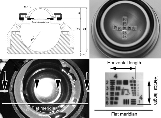
The model eye was filled with balanced salt solution at room temperature, with care taken to remove all air bubbles. Toric aspheric IOLs, SN6AT5 (AcrySof IQ toric; Alcon Laboratories, Fort Worth, Texas, USA) and 311T5 (AF-1; HOYA Surgical Optics, Frankfurt, Germany) with a cylinder power of 3.0 diopters (D) or SN6AT9 (AcrySof IQ toric; Alcon Laboratories) and 311T9 (AF-1; HOYA Surgical Optics) with a cylinder power of 6.0 D were studied. The orientation of the toric IOL was adjusted so that the toric markings of the flat meridian were at the horizontal mark of the model eye ( Figure 1 ). Nontoric aspheric IOLs, SN60WF (AcrySof IQ; Alcon Laboratories) and NY-60 (AF-1 iMics 1; HOYA Surgical Optics) were used as controls. All of the IOLs had the same spherical power of +20.0 D and were centered on the optical axis of the eye.
Two 23-gauge chandelier light pipes (Alcon Chandelier lighting system; Alcon Laboratories) were inserted through 2 openings on opposite sides of the model eye at positions similar to the sclerotomy sites used during pars plana vitreous surgery ( Figure 2 ). A flat quartz contact lens (HOYA Corporation, Tokyo, Japan) or a wide-angle viewing contact lens (Mini Quad; Volk Optical Inc, Mentor, Ohio, USA) was placed on the cornea of the model eye to view the grating target. Viscoelastic material (Viscoat; Alcon Laboratories) was applied beneath the contact lens on the cornea.
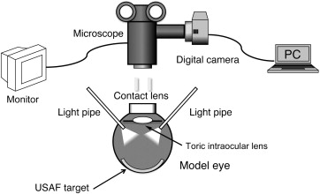
The grating target was photographed with a digital camera (EOS KISS X3; Canon Inc, Tokyo, Japan) through a surgical microscope (VISU140; Carl Zeiss Meditec, Tokyo, Japan) with a magnification of 25.5×. To evaluate the differences in the quality of the images quantitatively, the contrasts of the gratings in the photographs were measured using Photoshop CS4 (Adobe System Inc, San Jose, California, USA). The intensity at the center of the black stripe was set as I max and the intensity at the center of the white stripe was set at I min . The contrast was calculated as (I max – I min )/(I max + I min ) for each spatial frequency (cycle/mm). The results were compared for the different IOLs and for the flat or wide-angle viewing contact lens. For the toric IOLs, the contrast of the target lines that were parallel (horizontal) to the flat meridian of the toric lenses or the lines (steep meridian) that were perpendicular (vertical) to the flat meridian of the toric lenses was calculated separately.
The lengths of the horizontal and vertical borders of the square targets that were aligned to the flat meridian of the toric IOL ( Figure 1 ) were measured through both the flat contact lens and wide-angle contact lens. The ratio of the vertical to horizontal lengths (V/H) was calculated for each toric and aspheric IOL.
Wavefront Analysis of Toric and Aspheric Intraocular Lens in Model Eye
The toric and aspheric IOLs were implanted in the model eye and the flat meridian was set at 0 degrees. A wavefront analyzer (KR-1 W; Topcon Medical System Inc, Tokyo, Japan) was used to measure the cylindrical aberration of the IOLs for an image of 5 mm because the diameter of the optics of all the IOLs was 6.0 mm, and the valid optics of the toric IOLs was at least 5 mm. The internal aberrations that represented the aberrations of the IOLs were measured with the wavefront analyzer. In the device, the internal aberration was calculated to subtract the corneal aberration of the model eye from the aberration of the whole eye.
Statistical Analyses
Statistical analyses were performed by Student t tests using Microsoft Office Excel 2007 (Microsoft, Redmond, Washington, USA). A P value <.05 was taken as statistically significant.
Results
Contrast of Grating Targets Through Flat Contact Lens
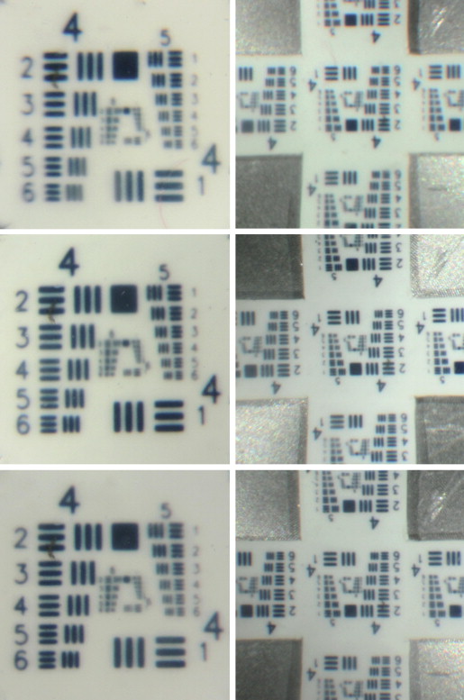
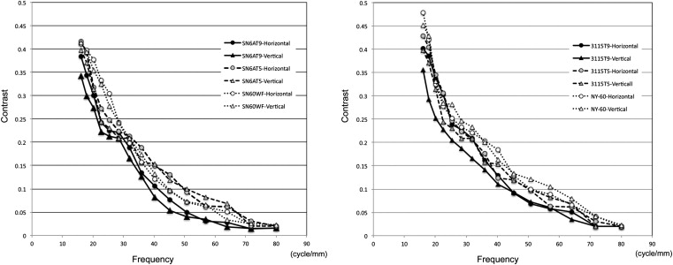
The contrasts of the gratings that were oriented vertical and horizontal to the flat meridian of the toric SN6AT9 IOL viewed through flat contact lens were significantly lower than those through the aspheric SN60WF at 16 cycle/mm ( P = .002, P = .023, respectively). However, the contrasts of the gratings oriented vertically and horizontally were not significantly different for 32 cycle/mm ( P = .097, P = .116, respectively) and 64 cycle/mm ( P = .554, P = .197, respectively; Table 1 , Figure 3 ). The contrasts of the grating in the vertical to the flat meridian through the toric SN6AT5 IOL were significantly lower at 16 cycle/mm ( P = .028) but not at other spatial frequencies, nor at other frequencies for the horizontal line.
| Toric IOL Model | Direction to the Flat Meridian | Frequency (cycle/mm) | Flat Contact Lens | Wide-Angle Contact Lens | ||
|---|---|---|---|---|---|---|
| Contrast | P Value a | Contrast | P Value a | |||
| SN6AT9 | Vertical | 16 | 0.342 | .002 | 0.215 | .062 |
| 32 | 0.166 | .097 | 0.080 | .411 | ||
| 64 | 0.019 | .554 | 0.003 | .667 | ||
| Horizontal | 16 | 0.384 | .023 | 0.223 | .079 | |
| 32 | 0.189 | .116 | 0.080 | .275 | ||
| 64 | 0.028 | .197 | 0.005 | .667 | ||
| SN6AT5 | Vertical | 16 | 0.398 | .028 | 0.238 | .626 |
| 32 | 0.208 | .192 | 0.093 | .319 | ||
| 64 | 0.068 | .164 | 0.018 | .245 | ||
| Horizontal | 16 | 0.417 | .560 | 0.249 | .416 | |
| 32 | 0.213 | .242 | 0.105 | .370 | ||
| 64 | 0.062 | .184 | 0.015 | .423 | ||
| 311T9 | Vertical | 16 | 0.355 | .002 | 0.207 | .063 |
| 32 | 0.166 | .020 | 0.091 | .423 | ||
| 64 | 0.034 | .144 | 0.020 | .423 | ||
| Horizontal | 16 | 0.402 | .005 | 0.223 | .052 | |
| 32 | 0.188 | .039 | 0.093 | .219 | ||
| 64 | 0.051 | .324 | 0.030 | .423 | ||
| 311T5 | Vertical | 16 | 0.381 | .011 | 0.223 | .116 |
| 32 | 0.144 | .055 | 0.115 | .423 | ||
| 64 | 0.019 | .423 | 0.020 | .423 | ||
| Horizontal | 16 | 0.395 | .053 | 0.245 | .150 | |
| 32 | 0.155 | .212 | 0.120 | .457 | ||
| 64 | 0.033 | .423 | 0.026 | .250 | ||
a Student t test: SN6AT9 with cylinder power of 6.0 diopters (6.0 D, Alcon) and SN6AT5 (3.0 D, Alcon) were compared with SN60WF (nontoric IOL, Alcon). 311T9 (6.0 D, HOYA) and 311T5 (3.0 D, HOYA) were compared with NY-60 (nontoric IOL, HOYA).
The contrasts of the grating bars vertical and horizontal to the flat meridian viewed through the toric 311T9 IOL were significantly lower than through the aspheric NY-60 IOL with flat contact lenses at 16 cycle/mm ( P = .002, P = .005, respectively) and 32 cycle/mm ( P = .020, P = .039, respectively) but not at 64 cycle/mm ( P = .144, P = .324, respectively; Table 1 , Figure 4 ). The contrasts of grating vertical to the flat meridian through the toric 311T5 IOL were significantly lower at 16 cycle/mm ( P = .011) but not at 32 cycle/mm ( P = .055) and 64 cycle/mm ( P = .423). The contrasts of targets horizontal to the flat meridian through the toric 311T5 IOL were not significantly different at 16 cycle/mm ( P = .053), 32 cycle/mm ( P = .212), and 64 cycle/mm ( P = .423).
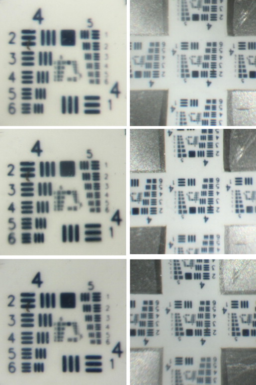
The contrasts of the horizontal and vertical grating bars through the toric SN6AT9 and toric 311T9 IOLs and the flat contact lens were higher at lower frequencies than those of toric SN6AT5 and toric 311T5 IOLs ( Figures 4 and 5 , Table 1 ). The contrasts of the horizontal and vertical grating bars through toric SN6AT5 and toric 311T5 IOLs with the flat contact lens were higher at lower frequencies than those of the aspheric SN60WF and NY-60 IOLs. The contrast of the horizontal grating bars through toric SN6AT9, SN5AT5, 311T9, and 311T5 IOLs with the flat contact lens tended to be greater than that of the vertical grating bars.
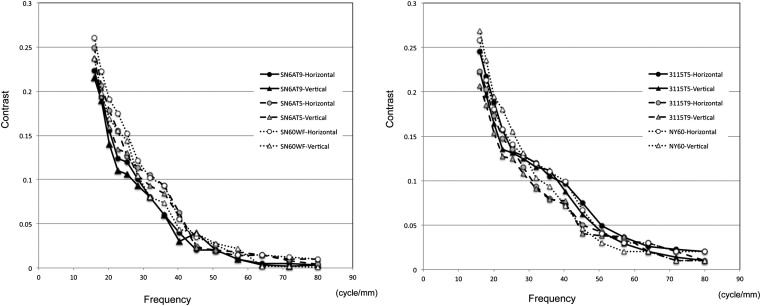
Contrast of Grating Targets Through Wide-Angle Viewing Contact Lens
The contrasts of the gratings bars vertical and horizontal to the flat meridian viewed through the toric SN6AT9 and SN6AT5 IOLs with the wide-angle contact lenses were not significantly different from that viewed through aspheric SN60WF for any spatial frequency of the grating ( Table 1 , Figures 3 and 6 ). Similar findings were made with the toric 311T9 and 311T5 IOLs with the wide-angle contact lenses ( Table 1 , Figures 4 and 6 ).
Stay updated, free articles. Join our Telegram channel

Full access? Get Clinical Tree


