Clinical Confocal Microscopy
H. Dwight Cavanagh
Patrick M. Ladage
W. Matthew Petroll
James V. Jester
BACKGROUND
The basic concept of confocal microscopy is derived from a clinical need to look into living tissues noninvasively in a more dynamic way than is provided by conventional light and ultrastructural microscopy. Fixation and mechanical sectioning of ex vivo specimens not only introduce artifacts in interpreting the function of living cells in tissues, but most important, make conventional microscopy a static technique. In 1955, Marvin Minsky (1) developed the concept of the first confocal microscope for studying neural networks in the living brain. The Minsky microscope condenser focused the light source within a small area of neural tissue with concomitant focusing of the microscope objective lens on exactly the same area. Because both condenser and objective lens had the same focal point, the microscope was termed confocal.
Since Minsky’s original concept, the optical theory of confocal microscopy has been formally developed by Wilson and Sheppard (2) and Sheppard and Cogswell (3). In the two modern confocal microscopes in general clinical or research use for corneal imaging, either a point or slit (i.e., optically diffraction-limited) light source is focused onto a small volume in the living cornea, and a simultaneously placed confocal point (pinhole) or slit detector is used to collect the resulting signal. This optical alignment excludes or reduces the out-of-focus reflected signal from above and below the focal plane (volume) defined by the objective lens, which contributes to the detected image, and the overall result is a marked increase in both lateral (x, y) and axial (z) resolution as well as contrast. Because only one tiny volume element of the cornea is observed by each point or slit source detector (trading field of view for enhanced resolution), a usefully wide field of view of the cornea as a whole must be regained by rapid mechanical scanning. This is achieved by a synchronous movement of the illuminator and detector. Therefore, the time resolution of the microscope is defined by the speed at which the single x, y field at a given depth can be scanned and recorded. Most important, however, by varying the plane of focus of both source and detector in the cornea along the z axis, the cornea can be optically sectioned noninvasively, traveling without moving. This remarkable property produces a true paradigm shift in the ability to image normal and pathophysiologic processes in situ at magnifications sufficient to resolve cellular and subcellular interactions over time (four-dimensional in vivo microscopy: x, y, z, time).
Because of concerns over retinal toxicity, the light source used to achieve either point or slit illumination for clinical confocal microscopy is restricted to white light in both currently U.S. Food and Drug Administration (FDA)-approved ophthalmic instruments.
The first practical application of confocal optical theory to the eye was the development in 1974 of the specular microscope by David Maurice (4), who demonstrated enhanced resolution and contrast in both endothelial and in situ keratocyte images that were obtained by narrowing a slit beam, thus reducing the volume of scattered light reaching the final image, an optical result identical to diffraction-limited pinhole or slit (source/detector) confocal imaging. Maurice’s approach led to the further refinement of a usable clinical specular microscope by Bourne et al. (5) and later by Koester (6), who used a scanning mirror system to move a slit over the tissue, rather than moving the object (the cornea) over the slit as Maurice had done. This basic design, still in widespread clinical practice in outpatient clinics and eye banking, provides a useful wide field view of the corneal endothelium in situ. Unfortunately, because specular microscopes use wide (500 μm) scanning slit detectors in place of a diffraction-limited pinhole (20 μm) or slit source illumination, and because the objective lens splits the light into two paths (incidence/detector), thus reducing by half the available effective numerical aperture (NA) of the objective lens (e.g., from 0.75 to 0.38), this approach provides much less lateral and axial resolution than a confocal microscope using an objective lens of the same NA.
Koester and colleagues (7) redesigned the objective lens to improve the optical sectioning ability of the contact-specular microscope, thus allowing images to be obtained
from all three cellular layers of the cornea. The redesigned system has several severe limitations, however. In addition to decreased optical resolution and contrast, use of the wide scan (500 μm) increases signal-to-noise background problems, which do not permit video recording of images viewed at a 1/20 scan (30 Hz) in real time. Instead, only static images are obtained, using a xenon-arc 35-mm flash camera with film pushed to grain resolution to improve contrast (8). Thus, the study of dynamic vision microphysiology is difficult to achieve with this method, and the high light levels achieved by the flash are toxic to the retina so that central corneal imaging is not possible past the pupillary edge, even when the pupil is constricted by topical pilocarpine to facilitate examination. For those clinicians who prefer this approach, however, a specular/confocal microscope is commercially available from Mission Research Associates (Laguna Beach, CA).
from all three cellular layers of the cornea. The redesigned system has several severe limitations, however. In addition to decreased optical resolution and contrast, use of the wide scan (500 μm) increases signal-to-noise background problems, which do not permit video recording of images viewed at a 1/20 scan (30 Hz) in real time. Instead, only static images are obtained, using a xenon-arc 35-mm flash camera with film pushed to grain resolution to improve contrast (8). Thus, the study of dynamic vision microphysiology is difficult to achieve with this method, and the high light levels achieved by the flash are toxic to the retina so that central corneal imaging is not possible past the pupillary edge, even when the pupil is constricted by topical pilocarpine to facilitate examination. For those clinicians who prefer this approach, however, a specular/confocal microscope is commercially available from Mission Research Associates (Laguna Beach, CA).
The design of the objective lens for in vivo confocal microscopy is also a critical element in the clinical usefulness of individual instruments. First, the z-axis spatial resolutions (actual volume element visualized) under confocal conditions is determined by the NA (light-gathering ability) and magnification of the objective lens (similar to reflecting telescopes of larger aperture). However, commercially available, high-numerical-aperture lenses usually possess short working distances, which limit the depth of tissue penetration (i.e., optical sectioning) that can be obtained. To solve this problem, two practical design approaches have been used: (a) a contact objective lens with an applanating tip that touches a drop of fluid on the cornea (eliminates a back-reflection “hot spot” in the center of the image); and (b) a noncontact objective lens not directly optically coupled to the cornea. As will be seen in a later discussion of the strengths and weaknesses of currently commercially available instruments, each of these approaches has significant functional consequences.
Proper orientation of the cornea during confocal viewing is an additional critical element in obtaining flat-field x, y plane images in which accurate three-dimensional epithelial keratocyte or endothelial cell shapes, areas, and interactions can be verified. Alignment of the objective lens in any orientation other than directly perpendicular to the corneal surface results in an oblique optical section through the cornea, which produces distorted three-dimensional views that cannot be quantified in the x, y, z volume. Thus, achievement of both perpendicularity and a zero z-axis reference point that does not shift and that allows true three-dimensional viewing and quantitation requires an optically coupled dipping-cone objective lens tip with either a concave or flat-front surface and a convex posterior surface that is concentric with the axial focal point. Such lenses “applanate” by riding on a coupling fluid cushion, and touch (if any) occurs only at the lateral edges of the field.
DESIGN AND FUNCTION OF THE PINHOLE DISK AND SCANNING SLIT CLINICAL CONFOCAL MICROSCOPE
The Pinhole Disk Microscope
In 1968, Petran and coworkers (9) developed the first scanning confocal microscope consisting of a single white light source and a modified Nipkow disk containing thousands of optical conjugate (source-detector), 20-μm (diffraction-limited) pinholes arranged in Archimedean spirals to permit maximum packing of holes without “cross-talk” signal between them (one hole leaking light into another). Rotation of the disk results in even “scanning” of the cornea by the source pinholes, whereas the conjugate pinholes prevent light from outside the optical volume, determined by the objective lens and pinhole diameter, from reaching a photodetector. Petran’s original tandem scanning design was adapted for viewing ocular structures in vivo in 1988 (10), and was originally commercially produced by Tandem Scanning Corporation (Reston, VA) (11). More recently, however, this microscope became commercially available from Advanced Scanning, Ltd. (New Orleans, LA). The optical light path for the tandem-scanning confocal microscope (TSCM) is shown in Fig. 10.1-1, and routine clinical use is illustrated in Fig. 10.1-2.
TSCMs in current clinical use are horizontally configured on a standard slit-lamp table for routine clinical use (Advanced Scanning, Ltd.) and use two specially designed dipping-cone objectives: 24×, 0.6 NA, 0- to 1.5-mm working distance, and 16× 0.40 NA, 0- to 8-mm working distance; each objective provides an x, y frame of 400 × 400 or 640 × 640 μm, respectively. For the tandem-scanning instrument, the position of the focal plane relative to the objective tip is varied by moving the lens within the
objective casing. Lens movement is controlled using an Oriel 18011 Encoder Mike Controller (Oriel Co., Stratford, CT) with a digital readout interfaced to a personal computer (PC) by a serial port. A program converts the encoder mike reading to the corresponding z-axis position (depth) to the focal plane in micrometers. This number is continuously updated and written into the user bit register of a time code generator (Fast Forward Model F30; Oriel Co.) through an RS232 interface. The time code generator writes this number onto the audio track of a super VHS recording; the depth can also be displayed on the video monitor during recording or playback. Thus, the depth of the focal plane in the tissue can easily be calibrated, and accurate quantitative four-dimensional imaging is possible with this system (12) (Fig. 10.1-3). The glass disks contain 64,000 20- or 30-μm pinholes with total optical transmittances of 0.25% or 0.33%, respectively; disk rotation speed is 900 rotations per minute, which produces “streak-free” images. The light path is composed of prisms and mirrors with a stable and easily maintained alignment. The light source is a 100-W mercury lamp; the instrument is currently approved by the FDA for clinical use in examining the eye (11).
objective casing. Lens movement is controlled using an Oriel 18011 Encoder Mike Controller (Oriel Co., Stratford, CT) with a digital readout interfaced to a personal computer (PC) by a serial port. A program converts the encoder mike reading to the corresponding z-axis position (depth) to the focal plane in micrometers. This number is continuously updated and written into the user bit register of a time code generator (Fast Forward Model F30; Oriel Co.) through an RS232 interface. The time code generator writes this number onto the audio track of a super VHS recording; the depth can also be displayed on the video monitor during recording or playback. Thus, the depth of the focal plane in the tissue can easily be calibrated, and accurate quantitative four-dimensional imaging is possible with this system (12) (Fig. 10.1-3). The glass disks contain 64,000 20- or 30-μm pinholes with total optical transmittances of 0.25% or 0.33%, respectively; disk rotation speed is 900 rotations per minute, which produces “streak-free” images. The light path is composed of prisms and mirrors with a stable and easily maintained alignment. The light source is a 100-W mercury lamp; the instrument is currently approved by the FDA for clinical use in examining the eye (11).
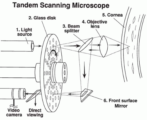 FIG. 10.1-1. The optical sectioning light path of the tandem-scanning confocal microscope. |
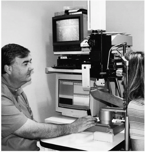 FIG. 10.1-2. Clinical examination with the tandem-scanning confocal microscope and video recording. |
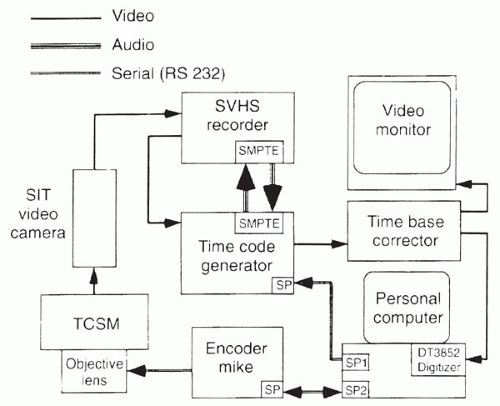 FIG. 10.1-3. Flow diagram of tandem-scanning confocal microscopy and image recording and analysis. |
The axial response of the TSCM system was determined with the 0.6 NA, 24× objective and the 0.25% transmittance, 20-μm pinhole disk by focusing through a perfect planar reflector (mirror) and measuring the reflected intensity curve; this yields a z-axis resolution of 9 μm (13). Lateral x, y resolution in vivo ranges from 0.5 to 1 μm.
One important limitation in obtaining high-frame speeds with the TSCM is the dramatic loss of light reaching the tissue because Nipkow disks transmit only 0.25% to 1% of the available light. This loss of luminance limits the amount of light reflected from low-contrast structures in opaque tissue. Thus, a low-light-level camera is needed for image acquisition. An additional obstacle to in vivo imaging is that the field of view is often moving owing to pulse and respiration. Video frames generated while an object is in motion are often blurred, giving poor resolution of cellular detail. Single frames generated by low-light-level cameras also suffer from significant noise produced by the
image intensifier. A standard technique for reducing the amount of random noise in a single image is to average several sequential frames. However, for image averaging to be successful, the sequential images must be perfectly registered, that is, there must be no positional changes between them. In many in vivo studies, there often is only a short pause between movements in which the frames are stationary and can be averaged successfully (12).
image intensifier. A standard technique for reducing the amount of random noise in a single image is to average several sequential frames. However, for image averaging to be successful, the sequential images must be perfectly registered, that is, there must be no positional changes between them. In many in vivo studies, there often is only a short pause between movements in which the frames are stationary and can be averaged successfully (12).
Stay updated, free articles. Join our Telegram channel

Full access? Get Clinical Tree


